Information and Downloads
| Generator | Khronos glTF Blender I/O v1.5.17 |
|---|---|
| Copyright | CC-BY 4.0 Copyright 2021 Analytical Graphics, Inc. Model and Textures by Ed Mackey. |
| Source | KhronosGroup/glTF-Sample-Assets |
| File size | 56.18 kB |
 Source glTF Source asset from
KhronosGroup/glTF-Sample-Assets
 three r185 Converted with upstream three.js 0.185.0
 Needle Converted with Needle Engine 5.1.2 USDZExporter
 Blender 5.1 Converted with Blender 5.1.2
  Adobe glTF Converted with OpenUSD 26.05 and Adobe glTF file-format plugin 2026.03
  GUC Converted with GUC 0.5
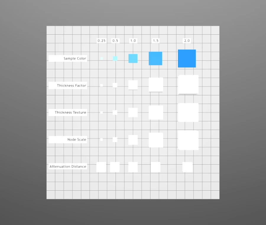
 Omniverse Converted with Omniverse Kit 105.0
Description
Attenuation Test
Tags
Extensions Used
- KHR_materials_transmission
- KHR_materials_volume
Summary
Tests the interactions between attenuation, thickness, and scale.
Operations
- Display in SampleViewer
- Download GLB
- Model Directory
Screenshot
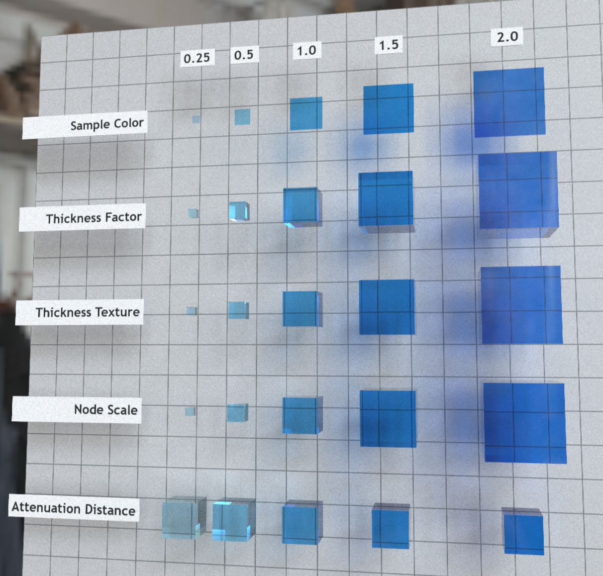
Path-traced render by the Enterprise PBR Sample Renderer, using IBL "Artist Workshop" by HDRI Haven. Turn off "autoscale scene" before loading in this particular renderer.
Description
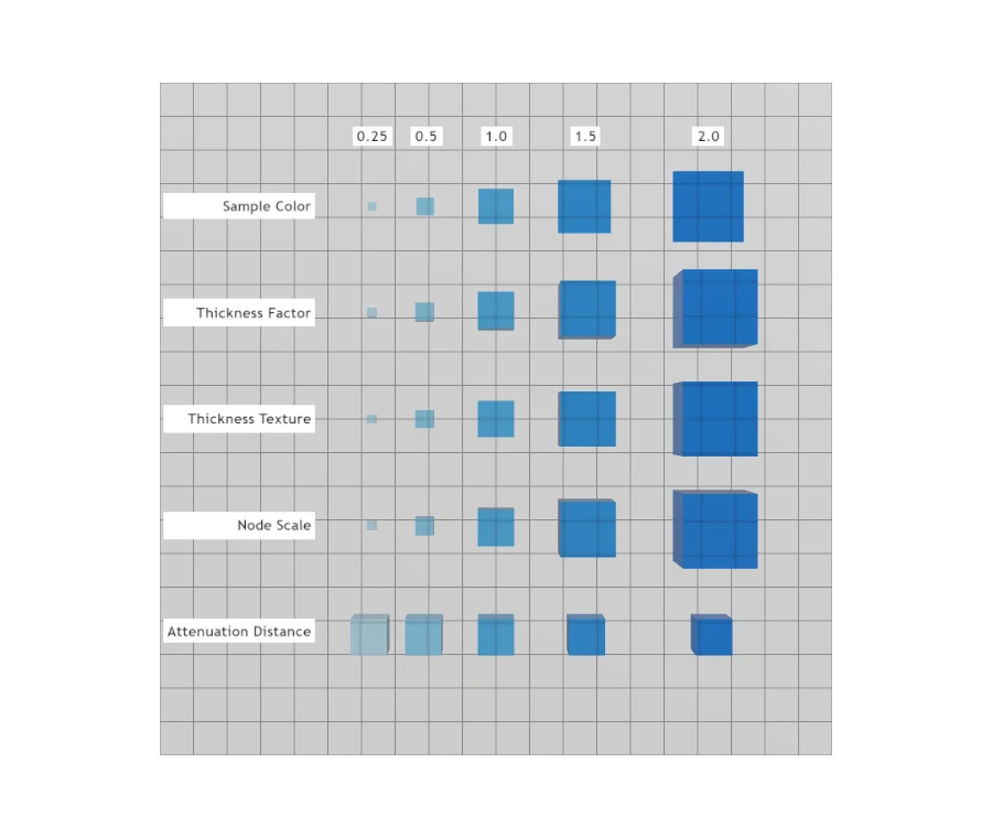
This model tests interactions between attenuation color, attenuation distance, and thickness in the KHR_materials_volume extension. The material on display here is intended to represent a tinted blue glass, where thinner or smaller chunks of the material are lighter blue, and larger or thicker chunks are deeper blue. The test should be viewed face-on, not at an angle, as the assigned thicknesses match the lengths of the cube edges, not the cubes' inner diagonals.
Generally, an implementation can pass the test offered by this model if it displays a uniform shade of blue in each vertical column. If any row is a different shade from neighbor rows, it likely indicates a problem.
Sample Color
The top row "Sample Color" does not use attenuation at all. It emulates the "correct" colors by varying the base color on the surface of each sample, according to the attenuation formulas given in the KHR_materials_volume specification. This row serves as an answer key for all of the other rows.
Thickness Factor
The next row "Thickness Factor" is the first test of the tinted blue solid material. The attenuation color and attenuation distance are constant across the row, but the cube meshes vary in size, and the thicknessFactor for each cube matches the length of one edge of the corresponding cube. A non-raytracing rasterizer can use the thicknessFactor to gauge the depth of the material, and adjust the material color according to the attenuation formulas mentioned above. A path-tracer or ray-tracer will merely test if thicknessFactor is zero (because zero means thin-walled, non-zero means volumetric), but the numeric thickness value will be ignored, and instead the world-space thickness of the geometry will be calculated by path tracing. If the camera is viewing mostly straight through the cubes, this should result in mostly the same thickness being discovered by path tracer calculations and by rasterizers reading the thickness value.
Thickness Texture
The "Thickness Texture" row is largely the same as the one above it, except the entire row is a single mesh, with a single material. This row's material has a thicknessFactor of 2.0, which is the thickness of the largest cube, and the cubes use a thicknessTexture to indicate which parts of this row's mesh belong to smaller cubes. As is typical for glTF, the final thickness value is the product of the factor (uniform) and the texture (sampled).
Node Scale
The "Node Scale" row tests the interaction between thickness and scale. Each cube on this row uses the same unit-size cube mesh, with the same material, attenuation, and thickness. Only the glTF node's scale is varied across the row. The thicknessFactor is given in the mesh's raw vertex space, but the attenuationDistance is a material property in world space. In a path tracer, larger nodes with larger cubes naturally produce deeper colors from attenuation. But a rasterizer must take the node's scale into account, adapting the thicknessFactor into world space before use with the material.
Attenuation Distance
In the final row, "Attenuation Distance", the cubes are a different size from all of the other rows. This row features all unit-size cubes, and the attenuation distance of each cube has been adjusted to be the inverse of the cube's thickness on the other rows. This means that although the size of these cubes may appear different, the shade of blue coloring of each cube should match the coloring of the rest of the column.
Legal
© 2021, Analytical Graphics, Inc.. CC BY 4.0 International
- Ed Mackey for Everything